High bandwidth cache-based covert channel attack
In a typical covert channel attack, we have two processes (a sender and a receiver) trying to communicate with each other though they are not allowed to do so by the security policies. While there are multiple cache-based covert channels possible, most of them have extremely low bandwidth.
This article discusses a new variant of the cache-based covert channel attacks that promises a high bandwidth.
Note: This article assumes basic understanding of cache based covert channels for the reader.
The setup
We have two processes, attached to two different cores. The processes are not allowed to communicate with each other by the security policies. Hence we cannot use signals, pipes or a file to transfer the data between the two. The hack in this system is to use the cache memory to facilitate the communication between our processes.
The processes have only very limited control over cache memory. A process cannot read the data cached by another process. Hence the attacker needs to be cleaver here and find other means of communication. This example attack uses the memory access time as a means of communication. The idea behind this is simple. A memory access which results in a cache hit is significantly faster than the access causing a cache miss. This difference in time required to access the data can be viewed as two states, like 'yes' and 'no'.
In the setup, our receiver will repeatedly access specific memory locations and time the access-time. Meanwhile, the sender will make sure that the receiver gets cache hits or misses as per the bits that need to be sent. We choose two memory addresses, one for communicating '0' and other for '1'. The bit being sent is determined by which memory location lave longer access time. Both sender and receiver will access the memory location multiple times to nullify the noise added by other processes.
Common method for sender-receiver synchronization
One of the important thing in the above method is the synchronization between sender and receiver. The receiver should know when does the sender start sending a bit, and how long. We have to ensure the synchronization under the following constraints.
We cannot guarantee that both programs start together. They cannot communicate with each other (Obviously, else why to even have a covert channel!). We also assume that we cannot process the "access-time vs time" graph and find the patterns. This is because this processing will require more storage and processing which implies a higher risk of detection. One way of tackling the problem is RTS/CTS based approach using other memory locations. Though this method has good confidence in synchronizing, this makes the whole communication slow.
The new synchronization method
We introduce a new synchronizing strategy that promises a speedup of at least 100
times (This can be higher but with a risk of a higher probability of
error). In this method, sync the bit transmissions using wall clock time. Each
transmission will occur during a fixed time slot. This is defined as a
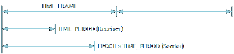
The program was tested on 8-way set associative L1 cache with 64 lines per block and each line of size 64 bytes. The total size was 32 kB. The addresses can be divided as 3 bits for set, and 6 bits each for block and line. To force a cache miss, the sender must access all 8 sets that map to the same memory location.
To determine the values of the various parameters discussed, a graph of "frequency of different access-times" vs "access-time" was plotted. Figure 2 and 3 show the graph when only the receiver is active. Figure 4 and 5 show the graph when both receiver and sender are active. The first set can be used to measure the cache hit time and the latter set to measure the cache miss time. The time is measured in CPU clock cycles. Both the above figures show roughly a time of 170 clocks to access a memory for a cache hit.
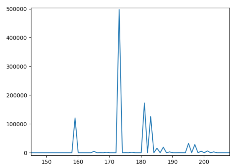
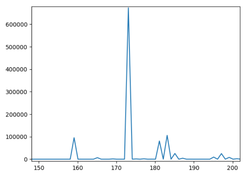
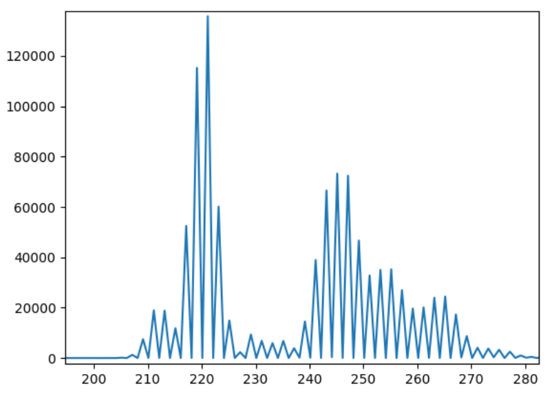
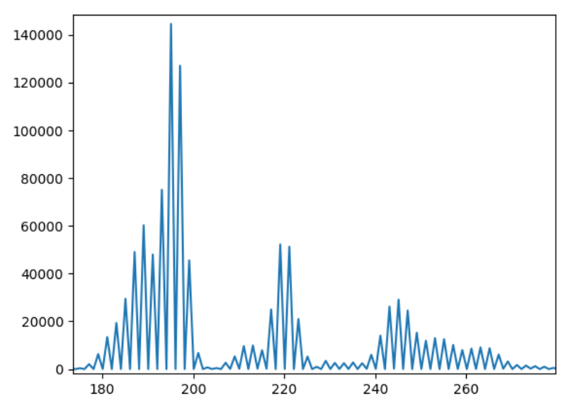
From the graph, we can see that the maxima for cache hit occurs roughly
around 170-175, while for a cache miss it occurs between 190-220. The
The value of
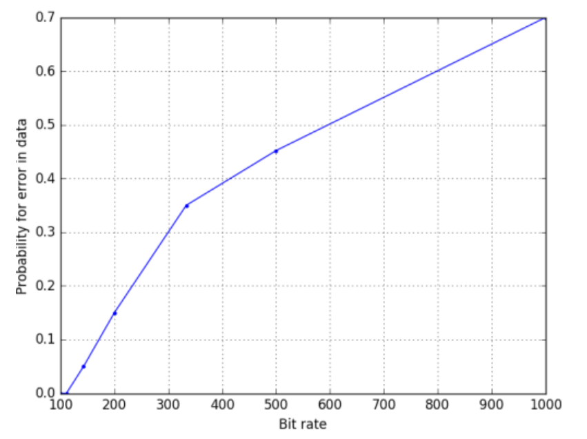
The error rate for 100-200 bit rate was manageable, but it was too high beyond this.
Improving the error rate
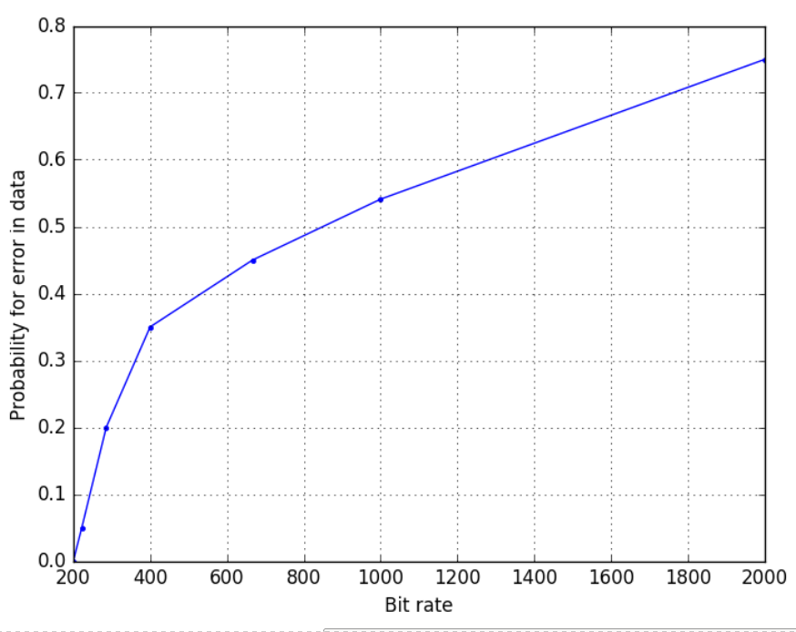
The error rate can be improved by adding another channel along with the existing one. This way, 2 bits can be communicated in the same time frame. This can probably be thought of as analogous to FDM where a different band is being used to transmit data simultaneously. The expectation is that the error vs bit rate should halve. This is what was obtained as shown in Figure 7.
Another way of improving the error rate would be to use a RTS/CTS based approach or ACK/NAK based control. The example of syncing using odd/even bit is also effective however, it uses two memory locations but only performs slightly better that the performance shown in Figure 6 which uses a single channel.
Courtesy:
Thanks to Rajat, my classmate and teammate for this project for his contributions.
The end